Harmonics & Total Harmonic Distortion (THD)
How switching actions and non-linear loads distort clean power grids.
What is a Harmonic?
A harmonic is a wave whose frequency is an integer multiple of the fundamental grid frequency (e.g., 50 Hz base, with 2nd/3rd multiples like 100 Hz or 150 Hz). Combining them distorts the clean sine wave.
Why Do They Appear?
They are caused by fast semiconductor switching (PWM) and non-linear loads (like rectifiers) that pull current in sharp pulses rather than smooth waves.
Why Undesirable?
They cause equipment overheating, core losses in transformers, and electromagnetic interference.
Amplitude Decay
Higher-order harmonics naturally get smaller because higher frequencies carry less energy and attenuate faster.
3-Phase Advantage
Three-phase rectifiers naturally cancel lower-order ripples, providing much smoother DC outputs.
Interactive Harmonic Synthesis Laboratory
Harmonic Controls
Toggle components to see how they distort the fundamental wave.
Engineering Notes
Harmonic frequency is an integer multiple of the base grid frequency.
Measures total harmonic noise relative to the fundamental wave. Lower THD means a cleaner waveform.
RMS vs Average Values
Understanding effective heating power versus mathematical averages in AC systems.

What is RMS?
Root Mean Square (RMS) represents the effective heating power of an AC waveform, equivalent to a DC voltage that delivers the same thermal energy.
For a pure sine wave with Peak Voltage = 20 V, the RMS value is VRMS = Vm / √2 = 14.14 V.
When to Use Each?
- Average Value: Used mainly for DC output voltage and current calculations across linear components.
- RMS Value: Used when calculating true power, component thermal ratings, conductor sizing, and losses.
| Feature | Average Value | RMS Value |
|---|---|---|
| Definition | Mathematical mean value | Effective equivalent DC heating value |
| Primary Application | DC output evaluation | Power, component sizing & losses |
| Symmetric AC Cycle | Zero (0) | Always Positive (>0) |
Interactive RMS & Waveform Shape Comparison
Waveform Selection
Select different waveform shapes (Peak V = 20 V) to observe how RMS and shape factors change.
Sine wave distributes energy smoothly, yielding Vm / √2.
Engineering Notes
Sine wave distributes energy smoothly, yielding Vm / √2.
Power Electronics Academy
Learn how circuits work through simple, interactive visual guides.
Who Am I?
I'm Hamad Alasim, an Electrical Engineering graduate from King Saud University.
As an electrical engineering interested in power electronics, my goal is making complex engineering concepts easier to understand through simple visual guides.
Contact Me
The Core Concept
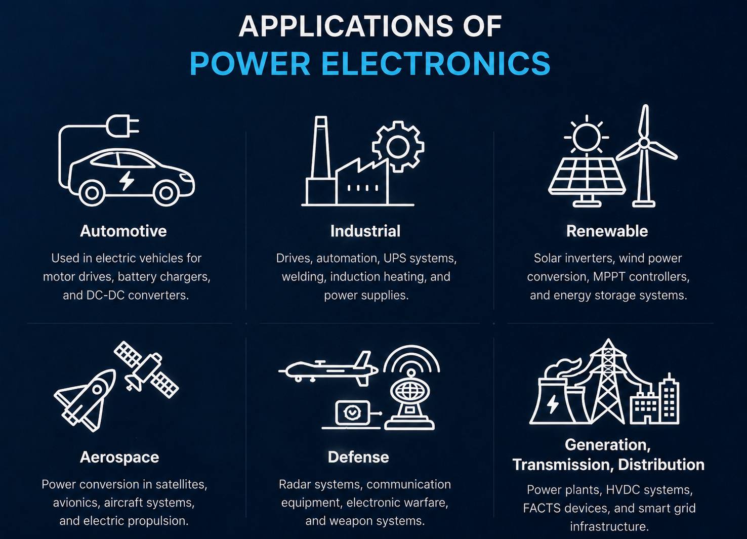
Power Electronics is the field of electrical engineering that controls and converts electrical energy using semiconductor switches. It allows us to efficiently change voltage, current, and power for different applications.
Introduction Fundamentals
Diode
A one-way valve that allows electrical current to flow in only one direction.
MOSFET / IGBT
Electronic power switch for fast ON/OFF control. MOSFETs suit high-frequency converters, while IGBTs are commonly used in higher-power systems.
Thyristor (SCR)
Turns ON with a gate pulse, but cannot be turned OFF by the gate. It switches OFF only when current becomes zero, so it is widely used in high-power rectifiers.
Resistor (R)
A component that opposes the flow of electrical current, converting energy into heat.
Capacitor (C)
A storage device that temporarily holds electrical energy in an electric field.
Inductor (L)
A coil of wire that stores electrical energy in a magnetic field, resisting current changes.
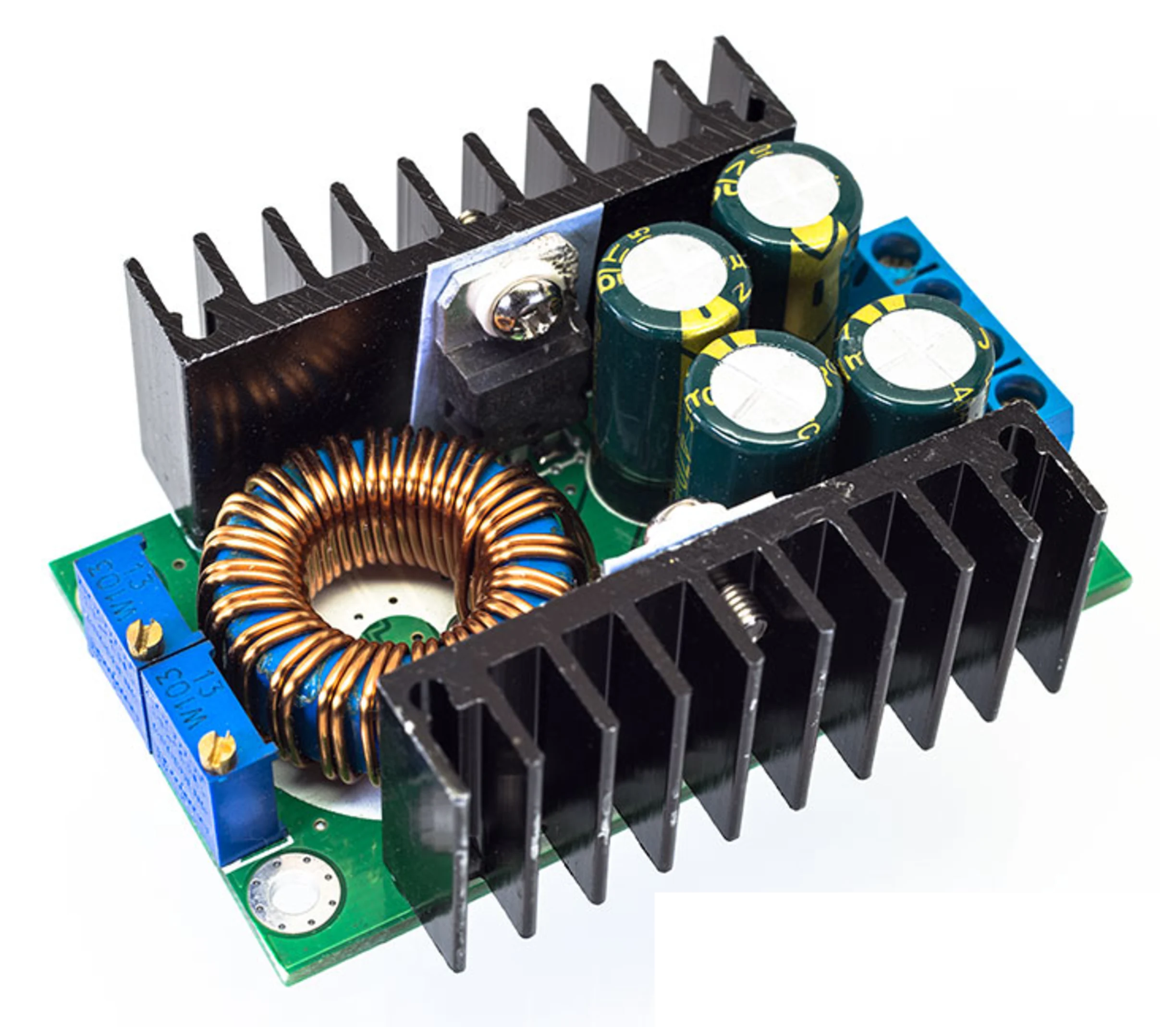
Buck Converter
A fundamental topology that STEPS DOWN DC voltage efficiently using high-frequency switching.
Before We Start – Engineering Assumptions
- Ideal components are assumed (no switching or conduction losses).
- Average inductor voltage over one switching period is zero.
- Average capacitor current over one switching period is zero.
- Input power ≈ Output power (ideal converter).
- In steady-state, the energy stored in the inductor and capacitor does not accumulate over one complete switching cycle.
The switch is open. The inductor releases its stored energy through the diode to maintain current.
Select a circuit component to inspect its properties.
Title
Numerical Laboratory
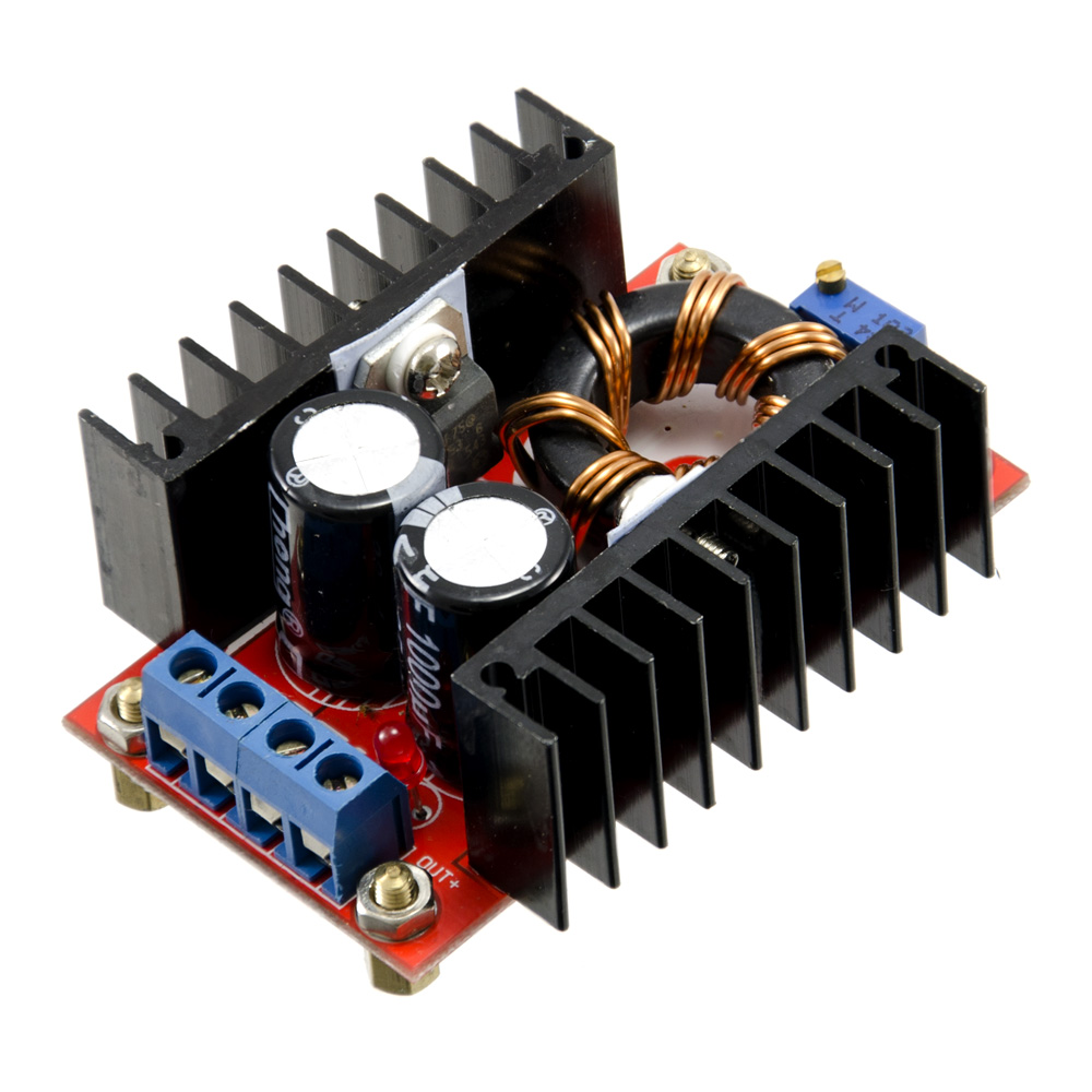
Boost Converter
STEPS UP DC voltage by accumulating magnetic energy in an inductor and pushing it into the output.
The switch is open. The inductor releases energy through the diode, boosting output voltage.
Select a circuit component to inspect its properties.
Title
Numerical Laboratory
Buck-Boost Converter
It can be both step up and step down voltage, while inverting the output polarity.
The switch is open. The inductor releases its stored energy into the capacitor and load, inverting polarity.
Select a circuit component to inspect its properties.
Title
Numerical Laboratory
Conduction Modes
Understanding Continuous (CCM) vs Discontinuous (DCM) Conduction Modes.
Continuous Conduction Mode (CCM)
In CCM, the inductor current never falls to zero during the switching cycle. A new cycle begins while energy still remains in the inductor. This is the standard operating mode for medium to heavy loads.
- Best for: High power applications.
- Advantage: Lower peak currents and less output ripple.
Discontinuous Conduction Mode (DCM)
In DCM, the inductor fully releases its stored energy, and the current drops to exactly zero before the next switching cycle begins. This naturally occurs when the load is very light.
- Best for: Low power or standby applications.
- Advantage: Fast dynamic response, no reverse recovery loss in the diode.
Converter Classification
The crucial difference between isolated and non-isolated power systems.
Non-Isolated Converters
The input source and the output load share a direct electrical connection (a common ground). There is no physical barrier separating the high-voltage side from the low-voltage side.
Topologies
Buck, Boost, Buck-Boost.
Pros & Cons
Smaller, cheaper, highly efficient. However, if the switch fails, high voltage can pass directly to the sensitive load.
Isolated Converters
Uses a high-frequency transformer to physically separate the input from the output. Energy transfers via magnetic fields across a physical isolation barrier.
Topologies
Flyback, Forward, Push-Pull, Full-Bridge.
Pros & Cons
Provides critical safety (galvanic isolation) and enables massive step-up/down ratios. However, they are larger, more complex, and more expensive.
Flyback Converter
An isolated version of the Buck-Boost converter. Stores energy in a coupled inductor (transformer) before transferring it.
The switch is open. The magnetic field collapses, transferring stored energy to the secondary load.
Select a circuit component to inspect its properties.
Title
Engineering Observations
The Flyback converter doesn't actually use a true transformer; it uses a coupled inductor. Energy is stored entirely in the core gap during the ON cycle, and transferred to the secondary during the OFF cycle. Because of this, it is limited to lower power applications but is extremely cheap and simple.
Forward Converter
An isolated version of the Buck converter. Transfers energy directly across the transformer *while* the switch is ON.
The switch is open. The freewheeling diode allows the inductor to maintain current flow to the load.
Select a circuit component to inspect its properties.
Title
What is a Rectifier?
The bridge between alternating grid power and the direct current our devices need.
The Conversion Concept
AC (Alternating Current) voltage continuously changes polarity, swinging from positive to negative. However, most electronic devices—from phones to computers to batteries—require a steady, single-direction DC (Direct Current) voltage.
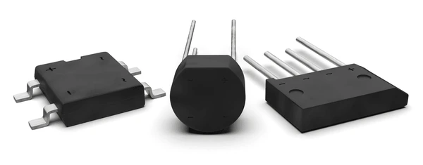
A rectifier is a circuit that converts AC to DC by allowing current to flow in only one direction.
Visual Comparison
Notice how the negative half is flipped to remain positive.
Common Applications
Half-Wave Rectifier
The simplest rectifier topology. It allows only the positive half-cycle of the AC source to pass to the load.
Select a half-cycle to observe the circuit behavior.
Select a circuit component to inspect its properties and behaviors.
Title
Numerical Laboratory
Engineering Notes
Controlled Half-Wave Rectifier
Uses an SCR (Thyristor) instead of a diode to control exactly when conduction begins during the positive half-cycle.
Waiting for gate pulse. The SCR blocks current even if forward-biased.
Select a circuit component to inspect its properties and behaviors.
Title
Numerical Laboratory
Delays the start of conduction.
Engineering Notes
Unlike a standard diode that conducts immediately at 0°, the SCR requires a gate pulse at Firing Angle (α). Increasing α directly reduces the average output voltage.
The Conduction Angle (γ) represents the duration the SCR actively allows current to flow before the zero-crossing turns it off naturally.
Full-Wave Bridge Rectifier
Uses four diodes in a bridge configuration to convert both the positive and negative halves of the AC cycle into DC.
Select a half-cycle to observe how the bridge routes the current.
Select a circuit component to inspect its properties.
Title
Numerical Laboratory
Because the bridge redirects both halves of the AC wave, the average DC output voltage is exactly double that of a Half-Wave rectifier.
Controlled Full-Wave Rectifier
Uses four SCRs to control exactly when power is delivered during *both* halves of the AC cycle.
Waiting for gate pulses at angle α to begin conduction.
Select a circuit component to inspect its properties.
Title
Numerical Laboratory
Because it is a full-wave bridge, the output is exactly double that of the Controlled Half-Wave rectifier for any given firing angle α.
Three-Phase Full-Wave Rectifier
Utilizes a three-phase AC supply and six individual diodes in a bridge configuration to deliver smooth, high-power DC with minimal ripple.
Select a phase to highlight its active state and conducting diode pair.
Select a circuit component to inspect its properties.
Title
Numerical Laboratory
Diode Conduction (120°)
Each diode conducts for 120° with a new conducting pair every 60°.
The Three-Phase Full-Wave Bridge (6-pulse rectifier) naturally produces a much higher average DC voltage with a fundamental ripple frequency of 6 times the supply frequency, making filtering significantly easier and cleaner than single-phase topographies.